The moment the liquid plastic enters the mold it’s going to start shrinking, and it is not going to do it uniformly unless you control it. This is how molded parts become warped, or end up with sink marks.
The good news is that Eck has you covered. Our expert sales engineers can guide you on how your part can be designed to reduce costs, create high quality uniform parts all while making sure it meets your functional needs! Below are general guidelines
Draft
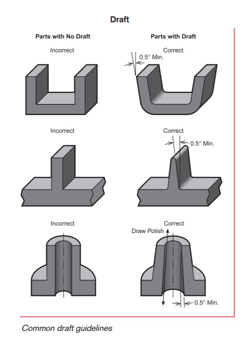 | To prevent parts from being damaged during ejection from the mold, a taper is applied to the faces of the part that parallel with direction of the mold opening. Recommended draft is as follows:
|
Coring and Wall Thickness
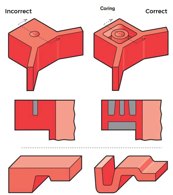 | Parts that are too thick will result in warping and sink marks. By shelling out thick areas a more uniform part can be achieved while also reducing material costs. Rigidity can still be maintained in a shelled part by placing ribs inside the shelled out part. Wall thickness details are below: Sink marks and warpage best avoided by designing your part with uniform wall thicknesses. Even further different polymers shrink at different rates. To yield the best results, Eck Plastics recommends using the wall thicknesses listed below: |
| Resin / Material | Inches |
|---|---|
| ABS | 0.045 - 0.140 |
| Acetal | 0.030 - 0.120 |
| Acrylic | 0.025 - 0.500 |
| Liquid Crystal Polymer | 0.030 - 0.120 |
| Long-fiber Reinforced Plastics | 0.075 - 0.150 |
| Nylon | 0.030 - 0.115 |
| PC (Polycarbonate) | 0.040 - 0.150 |
| Polyester | 0.025 - 0.125 |
| Polyethylene | 0.030 - 0.200 |
| Polyphenylene Sulfide | 0.020 - 0.180 |
| Polypropylene | 0.025 - 0.150 |
| Polystyrene | 0.035 - 0.150 |
| Polyurethane | 0.080 - 0.150 |
Tolerances
Resin / Material Tolerances
Fine Commercial
ABS Plus or minus .003 for the first 1 inch in length plus an additional .001 for every inch thereafter. Plus or minus .005 for the first inch in length plus .00125 for every inch thereafter
Acetal Plus or minus .005 for the first inch in length plus .00125 for every inch thereafter Plus or minus .005 for the first inch in length plus .00125 for every inch thereafter
Acrylic Plus or minus .0035 for the first inch in length plus .001 for every inch thereafter Plus or minus .005 for the first inch in length plus .00125 for every inch thereafter
Liquid Crystal Polymer Plus or minus .005 for the first inch in length plus .00125 for every inch thereafter Plus or minus .005 for the first inch in length plus .00125 for every inch thereafter
Long-fiber Reinforced Plastics Plus or minus .005 for the first inch in length plus .00125 for every inch thereafter Plus or minus .005 for the first inch in length plus .00125 for every inch thereafter
Nylon Plus or minus .0025 for the first inch in length plus .00125 for every inch thereafter Plus or minus .00475 for the first inch in length plus .00125 for every inch thereafter
PC (Polycarbonate) Plus or minus .0025 for the first inch in length plus .00075 for every inch thereafter Plus or minus .004 for the first inch in length plus .001 for every inch thereafter
Polyester Plus or minus .003 for the first inch in length plus .0006 for every inch thereafter Plus or minus .004 for the first inch in length plus .00125 for every inch thereafter
Polyethylene Plus or minus .00425 for the first inch in length plus .0015 for every inch thereafter Plus or minus .007 for the first inch in length plus .002 for every inch thereafter
Polyphenylene Sulfide Plus or minus .005 for the first inch in length plus .00125 for every inch thereafter Plus or minus .005 for the first inch in length plus .00125 for every inch thereafter
Polypropylene Plus or minus .00425 for the first inch in length plus .00125 for every inch thereafter Plus or minus .007 for the first inch in length plus .002 for every inch thereafter
Polystyrene Plus or minus .003 for the first inch in length plus .00075 for every inch thereafter Plus or minus .0045 for the first inch in length plus .00125 for every inch thereafter
Polyurethane Plus or minus .005 for the first inch in length plus .00125 for every inch thereafter Plus or minus .005 for the first inch in length plus .00125 for every inch thereafter
Corner Design
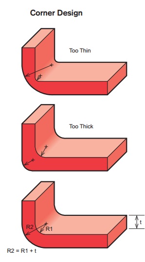 | The general practice of designing the outside corner radius of a part to one wall thickness larger than the inside radius will maintain a constant thickness through corners. |
Thickness Transitions
| By rounding or tapering transitions in part thickness will minimize read-through and possible surface blemishes. Additionally, the practice of material blending may reduce molded-in stresses and stress concentration associated with abrupt changes in thickness. |
Ribs
  | Providing ribs within a design reinforces strength and stiffness in molded parts without increasing overall wall thickness. Proper rib design involves five main criteria: thickness, height, location, quantity, and mold-ability. Other uses for ribs are as follows: |
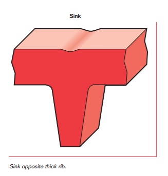
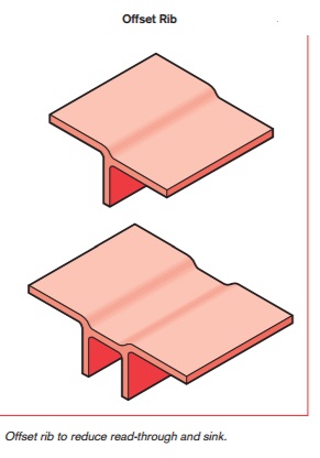
Rib Thickness
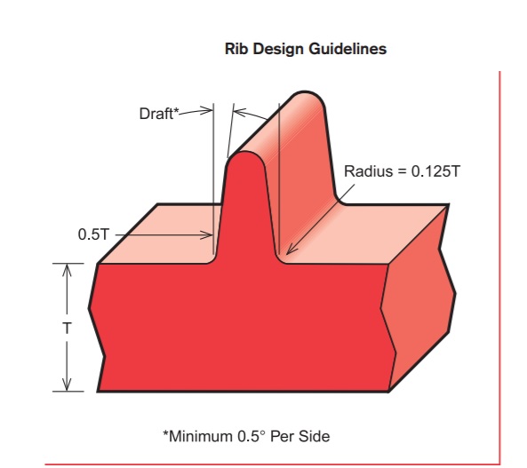 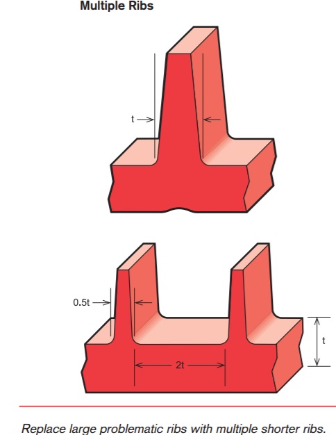 | There are many factors that determine the appropriate rib thickness for a part. Often if ribs are too thick they can cause sink, a cosmetic problems on the opposite wall surface. The material, rib thickness, surface texture, color, proximity to a gate, and a variety of processing conditions determine the severity of the sink. Rib Location & Quantity:
|
Bosses
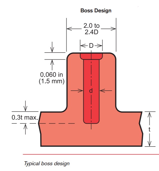  | Bosses are projections on a part designed to add strength, to facilitate alignment during assembly or allow for fastening additional parts. The most common variety consists of cylindrical projections with holes designed to receive screws, threaded inserts, or other types of fastening hardware. |
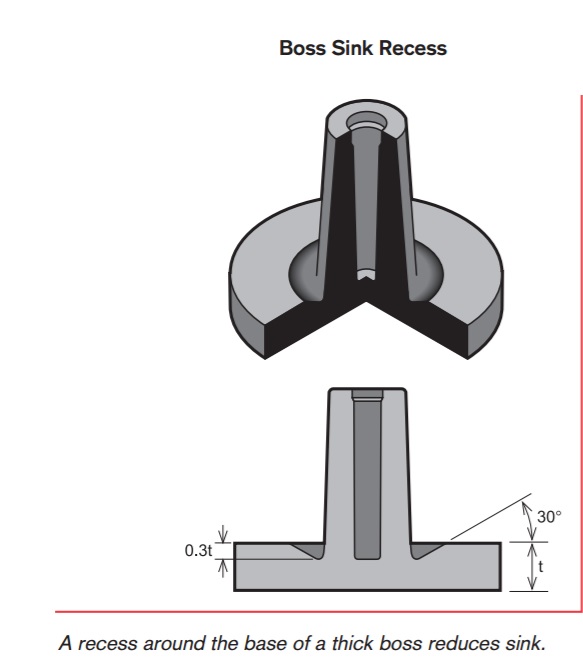
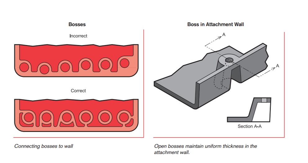 | General rule for design is the outside diameter of bosses should remain within 2.0 to 2.4 times the outside diameter of the screw or insert. It is suggested to avoid bosses that merge into sidewalls because they can form thick sections that cause lead to sink. |
 | Normally, the boss hole should extend to the base-wall level, even if the full depth is not needed for assembly. Shallower holes can leave thick sections, resulting in sink. Deeper holes reduce the base wall thickness, leading to filling problems, knit lines, or surface blemishes. Because of the required draft, tall bosses (those greater than five times their outside diameter) can create a filling problem at their top or a thick section at their base. Additionally, the cores in tall bosses can be difficult to cool and support. Think about coring a tall boss from two sides or extending tall gussets to the standoff height instead of than the whole boss. |

The Eck Plastic Arts Partnership Promise:
Hire and train good PEOPLE. Execute precise PROCESSES. Deliver quality PARTS.
We believe through our quality PEOPLE and the focus on continually improved PROCESSES we deliver the highest quality plastic PARTS ensuring your confidence in a long-term partnership.