Design Guidelines
There are two things that you want to mitigate when designing a part for injection molding, tooling (mold) cost, and to avoid sink/warp of the finished part. We can build a mold just about any way you want, but that doesn’t always mean that it is cost effective or that the tool will yield the desired part.
The moment the liquid plastic enters the mold it’s going to start shrinking, and it is not going to do it uniformly unless you control it. This is how molded parts become warped, or end up with sink marks.
The good news is that Eck has you covered. Our expert sales engineers can guide you on how your part can be designed to reduce costs, create high quality uniform parts all while making sure it meets your functional needs! Below are general guidelines
Draft
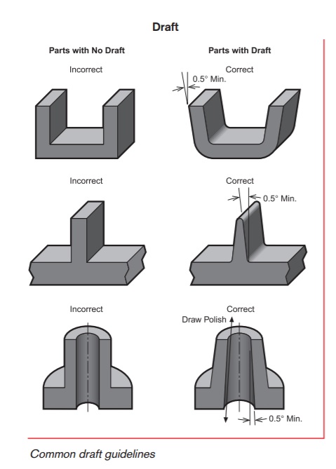
To prevent parts from being damaged during ejection from the mold, a taper is applied to the faces of the part that parallel with direction of the mold opening. Recommended draft is as follows:
- Draft all surfaces parallel to the direction of mold separation
- Angle walls and other attributes that are formed in both mold halve to assist ejection and retain uniform wall thickness
- As a general rule, use the standard one degree of draft plus one additional degree of draft for every 0.001 inch of texture depth
- Use a draft angle of at least one-half degree for most materials. Design permitting, use one degree of draft for easy part ejection. SAN resins typically require one to two degrees of draft.
Coring & Wall Thickness
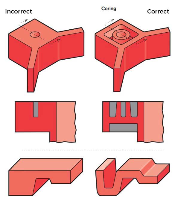
Parts that are too thick will result in warping and sink marks. By shelling out thick areas a more uniform part can be achieved while also reducing material costs. Rigidity can still be maintained in a shelled part by placing ribs inside the shelled out part. Wall thickness details are below:
Sink marks and warpage best avoided by designing your part with uniform wall thicknesses. Even further different polymers shrink at different rates. To yield the best results, Eck Plastics recommends using the wall thicknesses listed below:
| Resin / Material | Inches |
|---|---|
| ABS | 0.045 - 0.140 |
| Acetal | 0.030 - 0.120 |
| Acrylic | 0.025 - 0.500 |
| Liquid Crystal Polymer | 0.030 - 0.120 |
| Long-fiber Reinforced Plastics | 0.075 - 0.150 |
| Nylon | 0.030 - 0.115 |
| PC (Polycarbonate) | 0.040 - 0.150 |
| Polyester | 0.025 - 0.125 |
| Polyethylene | 0.030 - 0.200 |
| Polyphenylene Sulfide | 0.020 - 0.180 |
| Polypropylene | 0.025 - 0.150 |
| Polystyrene | 0.035 - 0.150 |
| Polyurethane | 0.080 - 0.150 |
Tolerances
The entire industry accepts that tolerances specified on a print for injection molded parts should vary with respect with the polymer used, and the overall size of the part. This is because industry wide tolerances greatly rely on the molder’s ability to predict how the polymer will shrink as it changes from a liquid to solid both inside the mold, and after the part has been ejected. Below is a chart that specifies generally accepted tolerances for the injection molding industry.
| Resin / Material | Tolerances | |
|---|---|---|
| Fine | Commercial | |
| ABS | Plus or minus .003 for the first 1 inch in length plus an additional .001 for every inch thereafter. | Plus or minus .005 for the first inch in length plus .00125 for every inch thereafter |
| Acetal | Plus or minus .005 for the first inch in length plus .00125 for every inch thereafter | Plus or minus .005 for the first inch in length plus .00125 for every inch thereafter |
| Acrylic | Plus or minus .0035 for the first inch in length plus .001 for every inch thereafter | Plus or minus .005 for the first inch in length plus .00125 for every inch thereafter |
| Liquid Crystal Polymer | Plus or minus .005 for the first inch in length plus .00125 for every inch thereafter | Plus or minus .005 for the first inch in length plus .00125 for every inch thereafter |
| Long-fiber Reinforced Plastics | Plus or minus .005 for the first inch in length plus .00125 for every inch thereafter | Plus or minus .005 for the first inch in length plus .00125 for every inch thereafter |
| Nylon | Plus or minus .0025 for the first inch in length plus .00125 for every inch thereafter | Plus or minus .00475 for the first inch in length plus .00125 for every inch thereafter |
| PC (Polycarbonate) | Plus or minus .0025 for the first inch in length plus .00075 for every inch thereafter | Plus or minus .004 for the first inch in length plus .001 for every inch thereafter |
| Polyester | Plus or minus .003 for the first inch in length plus .0006 for every inch thereafter | Plus or minus .004 for the first inch in length plus .00125 for every inch thereafter |
| Polyethylene | Plus or minus .00425 for the first inch in length plus .0015 for every inch thereafter | Plus or minus .007 for the first inch in length plus .002 for every inch thereafter |
| Polyphenylene Sulfide | Plus or minus .005 for the first inch in length plus .00125 for every inch thereafter | Plus or minus .005 for the first inch in length plus .00125 for every inch thereafter |
| Polypropylene | Plus or minus .00425 for the first inch in length plus .00125 for every inch thereafter | Plus or minus .007 for the first inch in length plus .002 for every inch thereafter |
| Polystyrene | Plus or minus .003 for the first inch in length plus .00075 for every inch thereafter | Plus or minus .0045 for the first inch in length plus .00125 for every inch thereafter |
| Polyurethane | Plus or minus .005 for the first inch in length plus .00125 for every inch thereafter | Plus or minus .005 for the first inch in length plus .00125 for every inch thereafter |
Corner Design
Good corner design in plastic injection molded parts is crucial for several reasons. First, well-designed corners help distribute stress more evenly throughout the part, reducing the risk of weak points that could lead to failure during use. Sharp corners can create stress concentration, making the part more susceptible to cracking or warping. Additionally, smooth, radiused corners facilitate better material flow during the injection process, ensuring that the mold fills completely and reduces the chances of defects such as voids or short shots. Lastly, it simplifies the mold-making process, potentially lowering production costs and lead times.
Thickness Transitions
Ribs
Providing ribs within a design reinforces strength and stiffness in molded parts without increasing overall wall thickness. Proper rib design involves five main criteria: thickness, height, location, quantity, and mold-ability.
Other uses for ribs are as follows:
- They act as stops or guides for mechanisms
- Ribs locate and captivate components within an assembly
- They provide alignment in mating parts
Rib Thickness
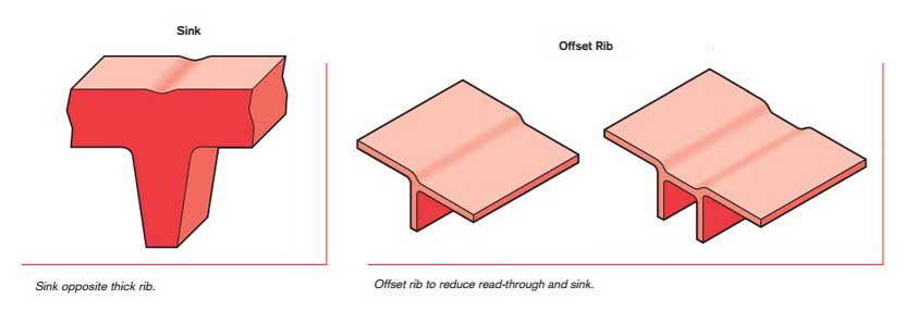
There are many factors that determine the appropriate rib thickness for a part. Often if ribs are too thick they can cause sink, a cosmetic problems on the opposite wall surface. The material, rib thickness, surface texture, color, proximity to a gate, and a variety of processing conditions determine the severity of the sink.
Rib Location & Quantity:
Proper thought should be used when deciding on the location and quantity of ribs within a part. For example, ribs added to increase part strength and prevent breakage may reduce the ability of the part to absorb impacts without failure.
- Furthermore, a grid of ribs added to ensure part flatness may lead to mold-cooling difficulties and warpage.
- Typically much easier to add than remove, ribs should be applied sparingly in the original design and added as needed to fine tune performance.
Bosses
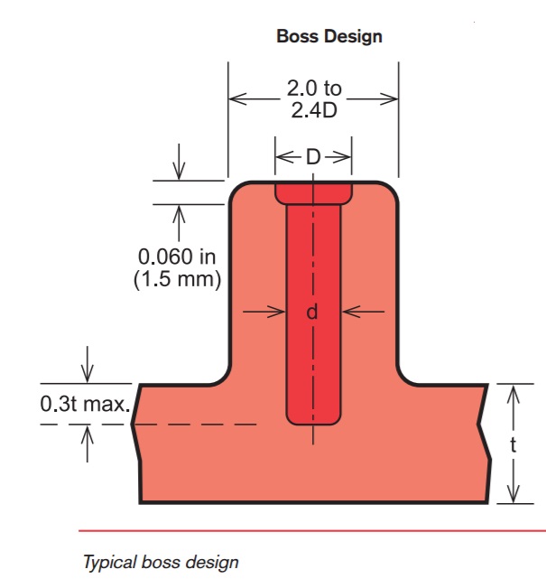
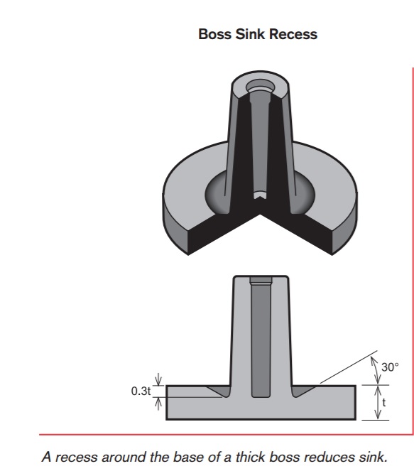
Bosses are projections on a part designed to add strength, to facilitate alignment during assembly or allow for fastening additional parts. The most common variety consists of cylindrical projections with holes designed to receive screws, threaded inserts, or other types of fastening hardware.
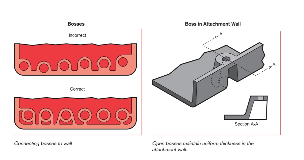
General rule for design is the outside diameter of bosses should remain within 2.0 to 2.4 times the outside diameter of the screw or insert. It is suggested to avoid bosses that merge into sidewalls because they can form thick sections that cause lead to sink.
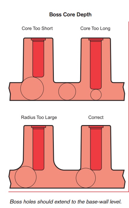
Normally, the boss hole should extend to the base-wall level, even if the full depth is not needed for assembly. Shallower holes can leave thick sections, resulting in sink. Deeper holes reduce the base wall thickness, leading to filling problems, knit lines, or surface blemishes. Because of the required draft, tall bosses (those greater than five times their outside diameter) can create a filling problem at their top or a thick section at their base. Additionally, the cores in tall bosses can be difficult to cool and support. Think about coring a tall boss from two sides or extending tall gussets to the standoff height instead of than the whole boss.
Injection Molding
Process that creates plastic objects by injecting molten plastic into a mold
Injection Molding
Process that creates plastic objects by injecting molten plastic into a mold
Thermoforming
Process of heating a thermoplastic sheet and applying a force to form it into or over a mold
Thermoforming
Process of heating a thermoplastic sheet and applying a force to form it into or over a mold
Plastic Fabrication
From advice on how to design for manufacturing, or assembly of plastic products
Plastic Fabrication
From advice on how to design for manufacturing, or assembly of plastic products
Product Finishing Operations
Delivering quality plastic parts may require more, and Eck Plastic Arts is ready to complete your project!
Product Finishing Operations
Delivering quality plastic parts may require more, and Eck Plastic Arts is ready to complete your project!
The Eck Plastic Arts Partnership Promise:
Hire and train good PEOPLE. Execute precise PROCESSES. Deliver quality PARTS.
We believe through our quality PEOPLE and the focus on continually improved PROCESSES we deliver the highest quality plastic PARTS ensuring your confidence in a long-term partnership.

